Thirteenth Week of Electronics Media
The thirteenth week of electronics media has ended. For this week, we focused on understanding motors and discussing our project ideas. Here is a recap of all that occurred this week.
On 3/31/25, I took the time to write down the notes from the labs before I got started on the motor examples. This is what I have recorded:
What is a Base Resistor?
- The resistor that goes between the Arduino output pin and the base of the transistor
- Keeps the transistor from drawing to much current
What is a Flyback Diode?
- A diode that is installed "backwards" in a circuit to keep high-voltage spikes (transients) produced by inductive loads from traveling through the circuit and damaging sensitive components
What is H-Bridge?
- A circuit that switches the polarity of 2 electrical contacts
- Looks like an H when made from scratch
What is a Solenoid?
- A coil that when energized produces a controlled magnetic field down through its center, which in-turn pushes or pulls a metal plunger; easy way to make a small back/forward motion
What are the 4 ways of activating a DC motor using an Arduino?
- Using Transistor
- Using a MOSFET
- Using a Relay (driven by a transistor)
- Using a Motor driver
What is a Transistor?
- A device that is used to switch electricity without any moving parts, uses current
- Can also be used to switch devices that exceed the Arduino's 5V limit
- Types:
- NPN transistors: A type of bipolar transistor with 3 layers that are used for amplifying circuits
- Ex: PN222 (In Kit), B547, 2N222, and 2N3904
- Any of these could take the place of PN222
- PNP transistors: A type of bipolar transistor that are used for controlling current
- Have to calculate value of base resistor to make sure we don't draw too much current (720mA) from the Arduino's digital pin
.png)
.png)
What is a MOSFET?
- A device that are capable of switching higher voltages and currents than transistors
- Similar structure to transistors but has a gate/drain/source pins instead of base/collector/emitter
- Uses certain voltage appearing at the gate pin
- Will act as a switch when they see a logic-level HIGH at their gate pin
- More expensive than transistors
What is a Relay?
- An electrically operated mechanical switch
- Has two parts
- Coil: where current flows through to create a tiny electromagnet
- Switch: the bit of metal the flip flops from the magnet
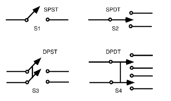
- Types:
- Single-Pole Single-Throw (SPST): On/Off
- Single-Pole Double-Throw (SPDT): Forward and Reverse
- A switch with multiple poles can switch multiple separate paths of electricity simultaneously with one flip of the switch
- Labels:
- COM (Common): Always connected to a wire
- Normally Connected (NC): Connected to COM until switch is on
- Normally Open (NO): Not connected to switch until switch is on

What is a L293D Motor Driver?
- A "Dual H-Bridge" or "Quadruple Half H" motor driver IC (Integrated Circuit)
- IC (Integrated Circuit): many are "Dual Inline Pin" (DIP) package whick looks like a black box with legs on both sides
- Legs can fold under accidentally and potentially break
- Can be sensitive to static electricity
- Are sensitive, advised to avoid soldering and instead use a dip socket
- Have pin numbered 1-16, starts at the left and makes it around counter clockwise with the end of the #1 pin identified by its notch
- Enable 1, 2 (Pin 1): When this pin is HIGH, the left part of the IC will work and when it is LOW, the left part won't work; master control of the IC left side
- Input (Pin 2): When this pin is HIGH, output 1 becomes HIGH, i.e. current will flow through output 1
- Output (Pin 3): Connected to terminal of motor 1
- GND (Pin 4, 5, 12, 13): Ground
- Output 2 (Pin 6): Connected to terminal of motor 1
- Input 2 (Pin 7): When this pin is HIGH, i.e., current will flow through Output 2
- VCC2 (Pin 8): Voltage required to run the motor, can be greater than VCC 1
- Enable 3,4 (Pin 9): When this pin is HIGH, right part of the IC will work and when it is LOW, the right part won't workl master control of IC's right half
- Input 3 (Pin 10): When HIGH, current will flow to Output 3
- Output 3 (Pin 11): Connected to one terminal of motor 2
- Output 4 (Pin 14): Connected to other terminal of motor 2
- Input 4 (Pin 15): When HIGH, current will flow through Output 4
- VCC1 (Pin 16): Provide 5V to IC

On 4/1/25, we discussed our project sketches. Out of all the sketches I've made, I decided to opt in for the "Manners Trash Can" where the piece would involve a trash can (with a motor on the bottom covered by a fake bottom) that would reject trash if you don't ask nicely beforehand.
On 4/2/25, I went back to the labs and performed each of the demonstrations. Here is what was recorded:
Example 1:
Example 2:
Example 3:
On 4/3/25, our class went through a servo motor demonstration. Here is the demonstration:
Example 1:

Comments
Post a Comment